LWA Memo Series


Daily Dynamic Spectra from the LWDA site

The Specmaster spectrum monitoring system was recently developed by Brian Hicks and Nagini Paravastu at NRL. The GUI-driven system is controllable either locally or remotely (Internet), and was installed at the LWDA site by NRL's Paul Ray in July 2006. Its output is now available at our Specmaster Data website, developed by Robert Duffin (NRL/GMU), allowing one to view Daily Dynamic Spectra and special events from the "Big Blade" antenna at the LWDA site.

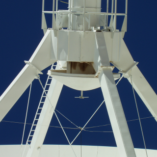
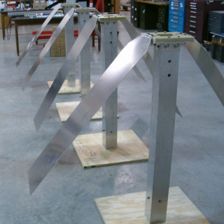
Measurements are now being obtained by our "Big Blade" antenna, featured in the top right panel at the Specmaster Data website. Larger than any of the 16 antennas that comprise the LWDA, Big Blade is a working prototype of the broader-bandwidth LWA dipoles that will operate over ~20-80 MHz. It is currently attached to our Specmaster spectrum analyzer that allows us to generate daily broad-band spectra. This is an important ongoing monitoring activity that is allowing us to develop a statistical characterization of the RFI environment around the LWDA site. So far, with the exception of a few well known bright narrow-band interfering signals, much of the LWA band appears relatively clean. We occasionally detect transient bursts from the sun, and as shown at the Specmaster Data website some of these events are being compared to simultaneous measurements obtained at other frequencies.

LWDA - Milestone Passed

First light with new receivers on 16 dipoles of LWDA - October 23, 2006

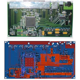
During the second half of October, Johnathan York, Aaron Kerkhoff, Charlie Slack and John Copeland from ARL:UT completed the installation of the LWDA hardware at the site and all is working beautifully. This includes both polarizations for all 16 dipoles, all 16 baluns, all the cables,the analog gain stages, the digital receivers, the adder boards, the control computer, the GPS receiver, the networked UPS, the internet switch, and the new A/C for the shelter. This is a major achievement; congratulations to everyone at ARL:UT who helped accomplish this, especially the four who spent an intense week in the desert getting it all together.

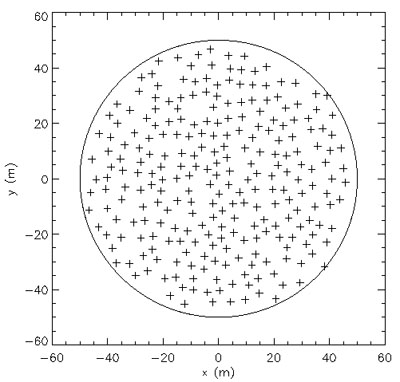
In addition, they were able to do careful phase and gain calibration of each of the antennas in the array and the calibrations look great. The phase calibrations were repeated on two different days and matched to better than 100 ps. Johnathan implemented a mode in the LWDA software to cycle through the array baseline by baseline doing a software FX correlator on each baseline, using the full 1.6 MHz bandwidth of the receiver. In this mode, it can measure all 120 visibilities in just a few seconds, and construct an image by superposing the 120 sine waves with the measured amplitudes and phases. Johnathan did this and had the process repeat all night. The result is shown in a great movie posted on the LWDA web page (click link above).

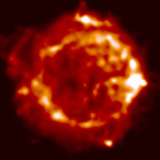
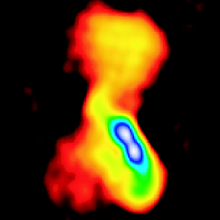
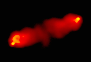
This is a major accomplishment - you can see Cas A, Cyg A, and Sgr A easily in the movie; there are hints of other sources, but obviously sidelobe confusion is a big issue. The next step which the team is planning is to integrate for several hours and clean the map.


LWA - Steps to Completion

Phased Development - summary

Time Phase Description Acronym

2004 0 Existing 74 MHz VLA VLA74
2006 - 2008 I
Funded!
Long Wavelength Development Array
+ Long Wavelength Array Station #1
LWDA
2007 - 2010 II 9-station
Long Wavelength Intermediate Array
LWIA
2010 - 2012 III LWA Core LWAC
2012 - 2014 IV High Resolution LWA LWA
2009 - V LW Operations and Science Center LWOSC

LWA Phase 0 (VLA74 - Complete)

Description


Phase 0 of the LWA consists of adding a 74 MHz capacity to the VLA by installing 2-meter dipoles at the prime focus of each antenna and associated receivers. Completed in 1998, this system, though simple and inexpensive, has opened up a new window on the long wavelength universe (see images below), produced a great deal of science, as well as valuable experience in long wavelength, high-resolution observation. This instrument is also being used to conduct the VLA Low-frequency Sky Survey (VLSS) which has already mapped half of the sky visible to the VLA at 74 MHz.
74 MHz Dipole on the VLA
74 MHz image of the supernova remnant
Cassiopeia A made with the new 74 MHz Pie-Town Link recently implemented by NRL and NRAO. (Image courtesy T. Delaney, PhD Thesis, UMN, 2004.)
74 MHz image of the giant radio galaxy
Hydra A

LWA Phase 1 (LWDA 2006-2008)

Description


Phase 1 of the LWA consists of the construction of two "development" LWA stations which will form the Long Wavelength Development Array (LWDA). The LWDA will be able to be used in stand-alone mode, or in combination with the VLA 74 MHz system. For more information of the station design, please see the station configuration memo in the LWA memo series.
Possible dipole configuration for a LWA station
Prototype dipoles used for testing.
The "beamformer" will combine the signals from all 256 dipoles in the station into a single beam.

LWA Phase 2 (LWIA 2007-2010)

Description


Phase 2 of the LWA will consist of the two Phase 1 stations plus another 6-7 new stations to be constructed out to baselines of about 150-200 km. This will provide enough baselines to become a stand-alone instrument (apart from the VLA) with full imaging capability. The main purpose is to be a prototype array for testing various ionospheric calibration schemes. However, with an imaging capability at 74 MHz of 4" resolution and 3 mJy/beam noise levels, Phase 2 will provide a huge leap in long wavelength observations, with much scientific potential. For more information on imaging capability, please see the LWA Phase II Imaging Capability memo in the LWA memo series.
Possible configuration for the LWA Phase 2
Synthesis UV coverage for the LWA Phase II in stand-alone mode. Simulated image of Cygnus A at 74 MHz with the LWA Phase II. The resolution of 4" is about 5 times better than can be achieved with the current VLA 74 MHz system.

LWA Phases 3 & 4 (LWAC 2010-2012; LWA 2012-2014)

Description


LWA Phases 3 and 4 will bring the LWA to completion. First, in Phase 3 (LWA Core), the compact core of about 15 stations will be built to fill in the short baselines. In Phase 4 (High Resolution LWA, other stations will be added to even out the UV coverage with baselines up to 500 km. At this point, the LWA will consist of 52 stations, with full imaging capability across the entire 23-80 MHz frequency range.

Artist's conception of complete LWA

LWA sensitivity and resolution compared to existing long wavelength instruments.