|
LWA Phase 0
(VLA74 - Complete) |
Description
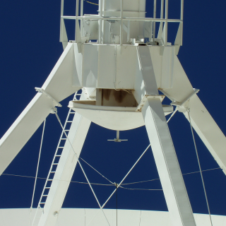
Phase 0 of the LWA consists of adding a 74
MHz capacity to the VLA by installing 2-meter dipoles at the prime
focus of each antenna and associated receivers. Completed in 1998,
this system, though simple and inexpensive, has opened up a new
window on the long wavelength universe (see images below),
produced a great deal of science, as well as valuable
experience in long
wavelength, high-resolution observation. This instrument is also
being used to conduct the VLA Low-frequency Sky Survey (VLSS) which has already
mapped half of the sky visible to the VLA at 74 MHz. |
|
|
74 MHz Dipole on the VLA |
 |
|
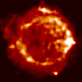
74 MHz image of the supernova remnant
Cassiopeia A made with
the new 74 MHz Pie-Town Link recently implemented by NRL and NRAO.
(Image courtesy T. Delaney, PhD Thesis, UMN, 2004.) |
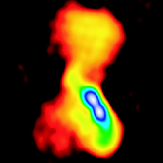
74 MHz image of the giant radio galaxy
Hydra
A |
|
LWA Phase 1
(LWDA 2006-2008) |
Description
Phase 1 of the LWA consists of the
construction of two "development" LWA stations which will form the
Long Wavelength Development Array (LWDA).
The LWDA will be able to
be used in stand-alone mode, or in combination with the VLA 74 MHz
system. For more information of the station design, please see the
station
configuration memo in the LWA memo series. |
|
|
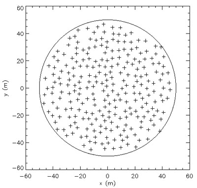
Possible dipole configuration for a LWA station
|
|
|
 |
|
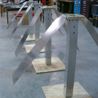
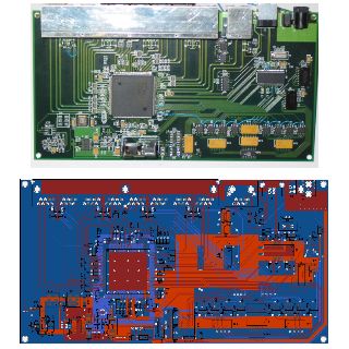
Prototype dipoles used for testing. |
The "beamformer" will combine the signals from all 256 dipoles
in the station into a single beam. |
|
LWA Phase 2
(LWIA 2007-2010) |
Description
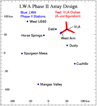
Phase 2 of the LWA will consist of the two
Phase 1 stations plus another 6-7 new stations to be constructed out
to baselines of about 150-200 km. This will provide enough baselines
to become a stand-alone instrument (apart from the VLA) with full
imaging capability. The main purpose is to be a prototype array for
testing various ionospheric calibration schemes. However, with an
imaging capability at 74 MHz of 4" resolution and 3 mJy/beam noise
levels, Phase 2 will provide a huge leap in long wavelength
observations, with much scientific potential. For more information
on imaging capability, please see the LWA Phase II
Imaging Capability memo in the LWA memo series. |
|
|
Possible configuration for the LWA Phase 2
|
 |
 |
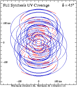
| Synthesis UV coverage for the LWA Phase II in
stand-alone mode. |
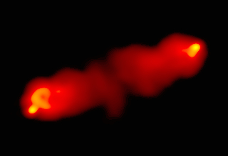
Simulated image of Cygnus A at 74 MHz with the LWA Phase II. The
resolution of 4" is about 5 times better than can be achieved with
the current VLA 74 MHz system. |
LWA Phases 3 & 4
(LWAC 2010-2012; LWA 2012-2014) |
Description
LWA Phases 3 and 4 will bring the LWA to
completion. First, in Phase 3 (LWA Core), the compact core of about
15 stations will be built to fill in the short baselines.
In Phase 4 (High Resolution LWA, other
stations will be added to even out the UV coverage with baselines up
to 500 km. At this point, the LWA will consist of 52 stations, with
full imaging capability across the entire 23-80 MHz frequency range.
|
 |
Artist's conception of complete LWA |
 |
|
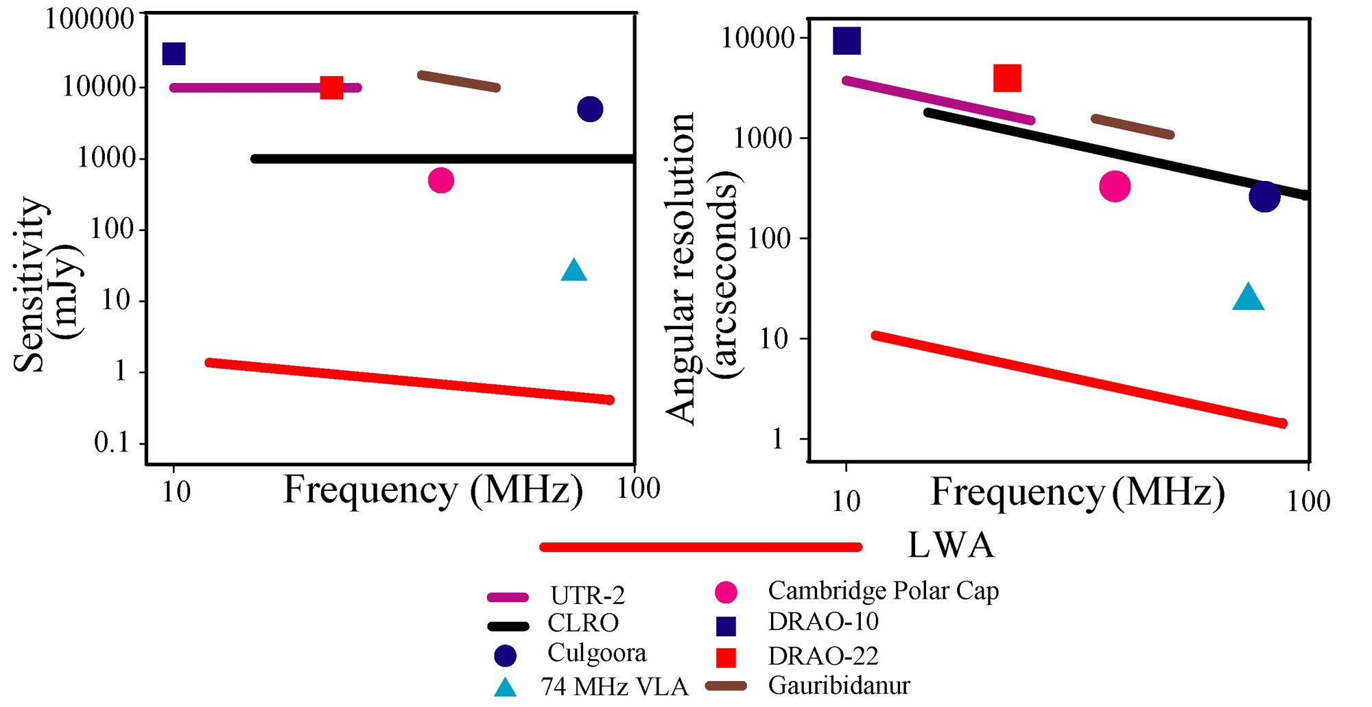
LWA sensitivity and resolution compared to
existing long wavelength instruments. |